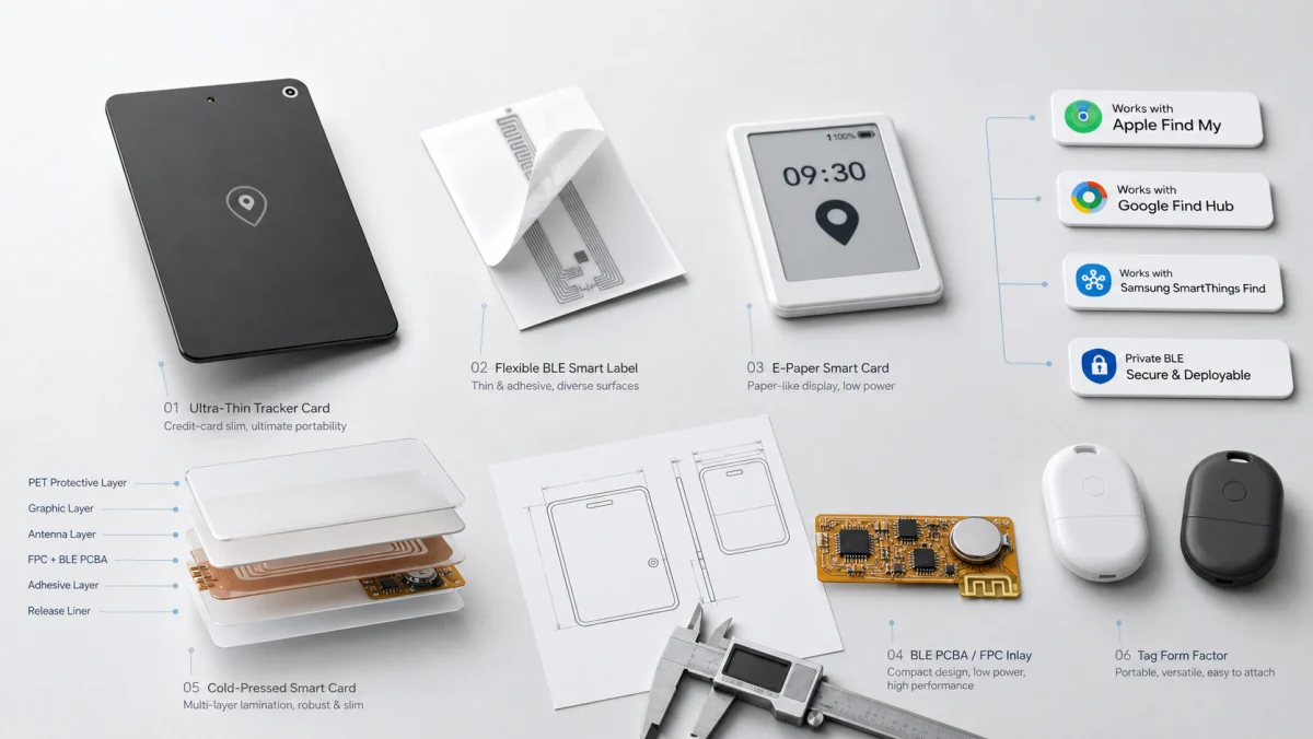
A cold-pressed smart card may look only slightly thicker than a conventional card, yet it can contain a flexible PCBA, battery, button, acoustic component, BLE or NFC antenna, and sometimes e-paper, light-energy harvesting, or sensing functions. The real engineering challenge is not fitting those parts inside the outline. It is keeping thickness, flatness, radio performance, button feel, acoustics, and long-term reliability under control at the same time.
Allocate thickness before placing components
Mechanical work normally starts from the finished-card target and works inward. Face stock, print layers, adhesive, reinforcement, PCBA, and battery all consume part of the thickness budget. A single local high point can become a visible bump or a stress concentration after pressing. Finished dimensions, target thickness, local tolerances, and bending requirements should therefore be agreed before package selection and material stack-up are frozen.
In a thin tracker card, the battery usually occupies the largest area while the acoustic device or switch may define the highest point. Their position must reflect loading direction, local cushioning, solder-joint protection, sound openings, and user interaction rather than the schematic alone.
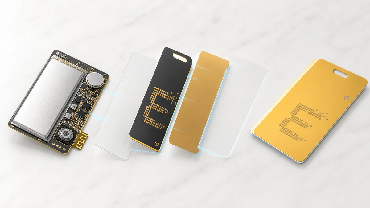
Five areas must be engineered together
1. PCBA and component high points
Create a component-height map that includes the IC, crystal, solder joints, switch, and acoustic component. Package choice, board thickness, controlled cavities, and reinforcement can reduce local pressure. Nominal bare-board thickness is not enough because solder, adhesive, and assembly tolerances accumulate.
2. Battery geometry and connection
Capacity cannot be considered in isolation. Area, thickness, tab direction, protection, and the power path all affect the structure. For a multi-year tracker-card target, it is usually better to model advertising, sleep, ringing, and abnormal states first, then select the battery, rather than compensating for uncertain firmware behavior with a thicker cell.
3. BLE and NFC antenna clearance
Batteries, metal parts, traces, and print materials near an antenna can change its match. The dielectric environment also changes when the board is encapsulated. Antenna position should be fixed early and measured again in a representative, fully assembled card. Projects combining BLE and NFC must also examine interaction between the antennas and the orientations used for tapping and remote finding.
4. Acoustic path and button feel
A tracker needs an audible response for nearby finding, but a thin card leaves little room for an acoustic cavity. Sound output depends on the transducer, opening area, cover material, and bonding method. Button travel, feedback, and accidental activation likewise need to be checked in the complete card rather than on the bare PCBA.
5. Test access and production fixtures
If every test point disappears after pressing, debugging and rework become expensive. Programming, power, RF, and functional-test access should be planned during hardware design. Critical dimensions and test steps can then move into the pilot build instead of being improvised after tooling is released.
Validation changes from prototype to production
Engineering prototypes answer whether the structure works: Is the card flat? Is the button usable? Is the sound clear? Does the assembled radio meet the project target? Pilot production shifts the question to repeatability: Do material lots, adhesive amount, press parameters, registration, and functional tests remain inside a stable process window? Volume production then turns those windows into work instructions and inspection criteria.
Provide finished dimensions and thickness, target ecosystem, battery-life objective, acoustic and button requirements, print concept, operating environment, estimated volume, and certification plan. Yuli supports custom hardware, firmware adaptation, certification preparation, pilot builds, and cold-pressed card manufacturing. Product positioning, channels, and final brand design remain with the customer.
Most failures do not belong to one discipline
A visible bump can come from component height, uneven adhesive, or registration error. A battery-life gap may be caused by the cell, firmware advertising behavior, unexpected wakeups, or temperature. Reduced range may involve the antenna, surrounding materials, or nearby metal. Treating mechanics, electronics, firmware, and manufacturing as separate hand-offs creates repeated redesign. A shared constraint list from the start is more efficient.
For related capabilities, see Advanced Cold-Press Manufacturing, Cold-Press Card Manufacturing Process, and Cold-Press Performance Validation.